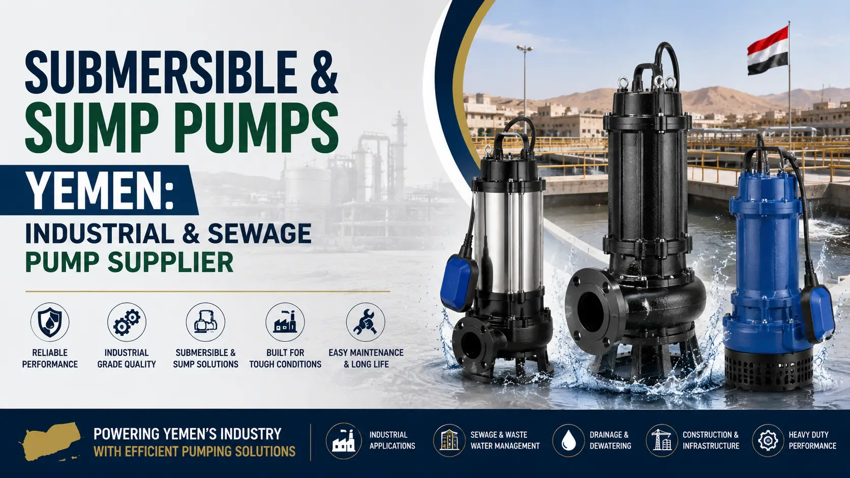
Industrial Submersible Pumps Yemen: Complete Selection & Application Guide
Some of the most severe water issues in the world can be found in Yemen. World Bank and UNICEF WASH assessments indicate that groundwater is the main source of water for millions of Yemenis, providing water to agriculture, municipalities, and industries. The choice of the submersible pumps in Yemen industrial projects and in communities is therefore not just a procurement issue, but also an issue of infrastructure that can significantly affect livelihoods, public health and economic productivity. This guide offers a comprehensive technical matrix for assessment, selection and procurement of industrial submersible pumps Yemen which engineers, project managers, NGO teams and procurement personnel must use to make informed judgements.
The principles governing the selection of the application remain the same whether it is deep borehole extraction for agriculture irrigation, rehabilitation of the municipal water supply, dewatering at a Marib facility, or transferring water for industry in an industrial zone in Aden, they all involve the same principles—flow rate, total dynamic head, fluid characteristics, power available, and material compatibility. This guide will discuss them in detail and application specific details to the most critical industrial sectors in Yemen.
What Are Industrial Submersible Pumps?
A Submersible Pump is a sealed electric pump that operates when it is completely immersed in the fluid to be pumped. Unlike surface mounted pumps, which have to lift the fluid up through the atmosphere, submersible pumps push the fluid up from below, allowing them to operate at depths much greater than those possible with suction lift technology. The pump motor and hydraulic assembly are permanently sealed, the motor is cooled by the surrounding hydraulic and not by air.
For industrial submersible pumps applications in Yemen, the equipment must be able to endure the harsh conditions it faces for long periods of time: high groundwater temperatures, high sand and mineral content groundwater, power fluctuations, and remote locations with limited maintenance access. The basic understanding of engineering principles of submersible pump technology is the cornerstone of proper equipment selection.
Core Operating Principle
The impeller or a series of impellers (in multistage designs) circulates fluid outward through centrifugal force when the pump motor is energized. As the fluid accelerates through the pump, its kinetic energy is transformed into pressure when it goes through the diffuser or volute, and the pressure forces the fluid to be pumped up to the surface through the discharge pipe. The water tightness of the motor casing keeps water from entering the motor windings and the shaft seal keeps the water from moving from the hydraulic section to the motor section.
In submersible designs, the motor is cooled by the pumped fluid running around the motor casing before it goes into the pump intake. This will mean that the pump cannot be placed in any borehole or sump where the fluid could go below the motor, which would lead to excessive motor overheating and winding failure.
How Industrial Submersible Pumps Work
Key Performance Parameters
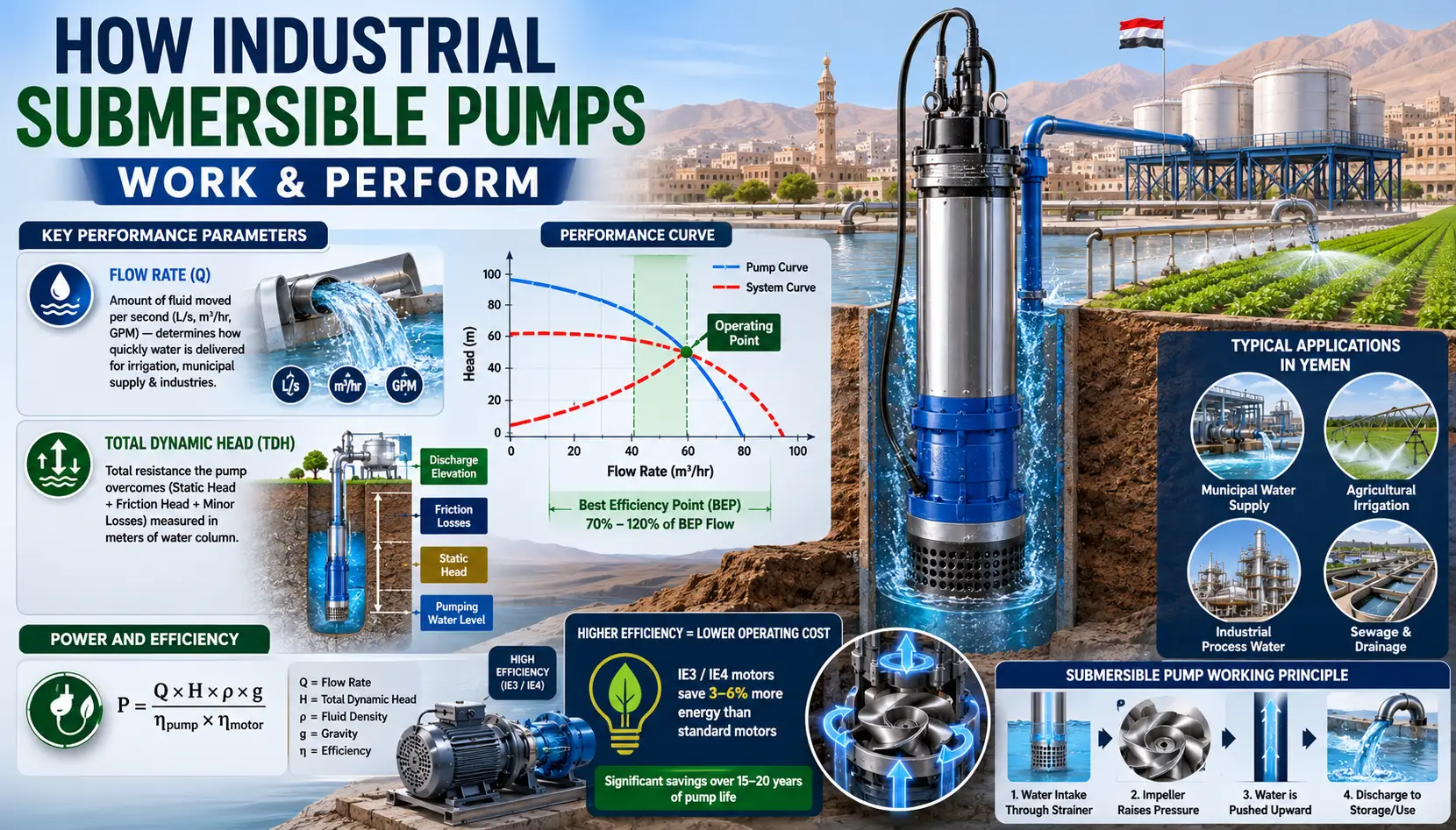
For any pumping selection two parameters of the hydraulic performance of the pump will have to be understood, namely flow rate and total dynamic head (TDH).
Flow Rate (Q) is the amount of fluid that the pump moves in a second, measured in liters per second (L/s), cubic meters per hour (m³/hr) or gallons per minute (GPM). In groundwater dependent agriculture areas of Yemen, the flow rate indicates how quickly fields can be irrigated and in municipalities having borehole water supplies, the flow rate indicates how many households the supply system can cover, in Sana'a or Taiz.
Total Dynamic Head (TDH) is the overall head or resistance that the pump has to overcome expressed in meters of water column. It is the total of the static head (vertical vertical from the pumping water level to the discharge point) and the friction head losses of the pipe system and minor losses at fittings and valves. The static head is 80 meters for a pumping water level at 80 meters below ground and a surface discharge elevation at 10 meters above ground (without pipe friction being taken into consideration).
A performance curve is a graph that shows the relationship between flow rate and head of the pump. The operating point is the point where the pump curve intersects the system curve which defines the actual flow rate and head the installation will produce. A proper selection must ensure that this operating point is in the pump's Best Efficiency Point (BEP) range which is generally considered to be between 70% and 120% of the BEP flow.
Power and Efficiency
Flow rate, head and pump efficiency are the factors that determine the pump input power, P = (Q × H × ρ × g) / (ηpump × ηmotor), with ρ being the density of the fluid, g the gravitational force, and η being efficiency factors. Pumps that operate at high efficiency ratings—the right pump with the correct motor size, to prevent continuous part-load operation—will directly cut operating cost for energy efficient pumps in energy-sensitive applications such as those in Yemen where power supply is expensive or intermittent. The premium efficiency motors, available for IE3 and IE4, can save energy 3-6% more than standard motors and this translates to a significant savings over the 15-20 year life of the pump.
Types of Industrial Submersible Pumps
Yemen procurement teams need to be familiar with multiple types of industrial submersible pumps for use in several different categories, including water, agriculture, mining, and municipal and industrial application.
Pump Type | Best Application | Depth Range | Fluid Type | Drive |
Borewell / Deep Well | Groundwater extraction, irrigation | Up to 300 m+ | Clean water | Electric motor |
Dewatering | Construction, mining, pit drainage | Shallow to 50 m | Dirty / silty water | Electric / diesel |
Sewage / Wastewater | Municipalities, industrial WWT | Up to 20 m | Solids-laden wastewater | Electric motor |
Multistage High-Head | Municipal supply, high-rise | Up to 300 m+ | Clean / treated water | Electric motor |
Slurry / Mining | Mine dewatering, slurry transfer | Varies | Abrasive slurries | Heavy-duty electric |
Solar Submersible | Remote agriculture, off-grid supply | Up to 200 m | Clean water | Solar PV array |
Borewell and Deep Well Pumps
The borewell pumps Yemen are centrifugal submersible pumps with multiple stages that are made specifically for the installation in narrow diameter boreholes which are most often 100 mm (4 inch) to 300 mm (12 inch) casing. The pump and motor assembly should be compact enough to fit into the borehole casing and leave a minimum of 25 mm clearance of the annulus size for the cooling water to flow through. Multiple pump stages are vertically stacked in series to provide further heads, allowing these pumps to be used in extreme groundwater extraction applications, such as pumping water from depths of more than 300 meters.
In agriculture applications, such as deep well submersible pumps, which are the most common pumps used by agriculture in Yemen, the agricultural regions around Sana'a, Taiz, and the Dhamaar and Amran agricultural areas are dominated by the use of multistage borewell pumps of 4” and 6”. These must be sized to the specific yield (sustainable extraction rate) of the borehole to prevent the water table being pulled down to the bottom of the borehole where it is pumped by the pump, leading to ‘dry running’ and pump failure.
Dewatering Pumps
Yemen mining and construction applications demand pumps that can effectively manage high water volumes with sand, silt and suspended solids. Dewatering pumps feature robust single-stage hydraulics and wear resistant impellers, allowing them to handle particulate matter without blockage or quick wear like a borewell pump does which can only pass clean water. Safe work conditions in pits and underground workings relies on dewatering for effective mining operations in Marib and other mineral producing areas of Yemen.
The selection of heavy duty dewatering pumps should consider maximum expected inflow rate which is normally derived from geological data and rainfall statistics and the required head of discharge (the distance the pump must move the water) and the maximum solids content present in the water. Sands in dewatering operations are particularly beneficial for the use of wear plates and chromium white iron impellers that resist abrasion and therefore help prolong the life of the pump.
Sewage and Wastewater Pumps
Sewage submersible pump Yemen municipalities, wastewater collection and treatment systems managed by municipal authorities in Aden, Al Hudaydah and Mukalla can be relied on for continuous operation in demanding wastewater handling duty. Sewage pumps have big passage impellers, whether of vortex, single channel or twin channel type, that will pass solid material up to 50–100 mm in diameter without blockage. They are located at low points in sewerage systems and lift water up and carry it on to a treatment plant or to a sewer outfall.
The proper choice of sewage pump motor ratings should consider the static head column with which the pumps are expected to start up, and the pump duty cycle should be based on actual usage patterns and not just on the average pump run time per day, as this varies greatly during the dry season, wet season, day and night.
Solar-Powered Submersible Pumps
Solar submersible pumps for irrigation systems in Yemen are a transformative technology for Yemen's large rural and agricultural areas, where electricity is unavailable or unreliable. The geographical location of Yemen between latitude 12° and 19° N, results in high solar irradiation throughout the year in almost every agricultural area, thus making solar PV use for pumping technically feasible in almost all areas of Yemen. Increased use in water supply and irrigation projects, supported by UNDP and NGOs, in Yemen has turned solar submersible pump systems into an effective and durable answer to water and irrigation problems in rural areas.
A solar pump system comprises of a submersible pump and motor, a solar controller (MPPT – Maximum Power Point Tracking), a PV array of the required size to pump the water and usually a water storage tank to store water for times when the sun is not shinning as much as during the day. When installed in an off-grid location, properly designed solar pump systems can be battery-less and rely on the storage tank for the energy buffer to provide the same or better level of reliability as a grid-connected system.
Applications in Yemen
Agricultural Irrigation — Water-Stressed Farming Regions
Groundwater use in Yemen is greatest for agriculture and occurs mainly in irrigated agriculture, which is mainly located in the highland plateau regions around Sana'a, in the Tihamma coastal plain, and around valley floor agricultural regions. Farmers in Yemen depend on submersible pumps to maintain their irrigation systems and in the basins where groundwater is over-extracted, the depths of boreholes can be greater than 100–150 meters in some areas, requiring the pump to deliver water at the head of multiple wells with limited maintenance from the farmers themselves.
Agricultural borehole pumping is typically 4 and 6 multistage borewell pumps with 3-phase electric motors or solar PV pumps. Sizing is very important, if pumps are too large, water is removed from the borehole at a rate that exceeds the ability of the aquifer to replenish the water, resulting in drawdown of the water table, pump dry-running and long-term loss of borehole yield.
See Industrial Valves for information on valves and flow control elements for irrigation distribution systems.
Municipal Water Supply — Sana'a, Aden, and Secondary Cities
Yemen water supplies are highly dependent on urban water supply systems with deep well submersible pumps operated by the Yemen water authorities in networks of municipal boreholes which are seriously over-extended, stressed by population growth, damage to infrastructure, and depletion of aquifers. The flow rates and heads for municipal borehole pumps are generally higher than agricultural borehole pumps and are required to be more reliable, because of the public health implications of the failure to secure water supply in high-density urban areas. In well managed municipal well systems, Redundancy (2 pumps per critical borehole) is standard practice.
UNICEF WASH and UNDP program for water infrastructure rehabilitation in Yemen have supported the replacement of many borehole pumps in Yemen's cities, and for some of these, upgrades of the pump have been carried out, with the pumps specified by internationally established manufacturers and the ability to provide locally available spare parts for maintenance.
Mining and Industrial Dewatering — Marib and Coastal Areas
Heavy duty dewatering pumps in Yemen are essential for the mining industry and industrial facilities to keep excavations, processing areas and industrial sumps safe and operational, by pumping out groundwater and processing water from these areas. Pump systems in mineral extraction regions must cope with fluctuating inflow rates, high solid loads, and in some cases, with operating for extended time periods for dewatering operations in Marib, dewatering operations for mining must deal with variable inflow rates, high solid loads and potentially multi-shift working schedules. Redundancy and fast spare parts delivery are essential operational needs.
Industrial Water Transfer — Aden Industrial Zone
Industrial water transfer pumps in Aden free zone and industrial port area that are required for process water supply, fire suppression system water supply, cooling water circulation, and wastewater collection in industrial facilities for operations in Yemen. They can be clean water, treated water or the process effluent, each having different material specifications for the wetted parts of the pump. Check out our Pumps & Fluid Handling products for pipeline parts and connection systems in industrial water transfer systems.
For pipeline components and connection systems used in industrial water transfer installations, explore our Pumps & Fluid Handling range.
For pump system safety components including pressure relief valves and system protection devices, see our Safety Equipment article.
Pump Selection Criteria
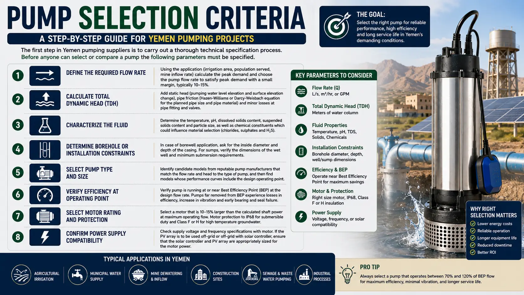
The first step in Yemen pumping suppliers is to carry out a thorough technical specification process. Before anyone can select or compare a pump the following parameters must be specified.
Step-by-Step Selection Process
Define the required flow rate. Using the application (irrigation area, population served, mine inflow rate) calculate the peak demand and choose the pump flow rate to satisfy peak demand with a small margin, typically 10–15%.
Calculate total dynamic head. Add static head (pumping water level elevation and surface elevation change), pipe friction (Hazen-Williams or Darcy-Weisbach equation for the planned pipe size and pipe material) and minor losses at pipe fitting and valves.
Characterize the fluid. Determine the temperature, pH, dissolved solids content, suspended solids content and particle size, as well as chemical constituents which could influence material selection (chlorides, sulphates and H₂S).
Determine borehole or installation constraints. In case of borewell application, ask for the inside diameter and depth of the casing. For sumps, verify the dimensions of the wet well and minimum submersion requirements.
Select pump type and size. Identify candidate models from reputable pump manufacturers that match the flow rate and head to the type of pump, and then find models whose performance curves include the design operating point.
Verify efficiency at operating point. Verify pump is running at or near Best Efficiency Point (BEP) at the design flow rate. Pumps far removed from BEP experience losses in efficiency, increase in vibration and early bearing and seal failure.
Select motor rating and protection. Remove and replace the motor housing. Select a motor that is 10–15% larger than the calculated shaft power at maximum operating flow. Motor protection to IP68 for submersible duty and Class F or H for high temperature groundwater.
Confirm power supply compatibility. Check supply voltage and frequency specifications with motor. If the PV array is to be used off-grid or off-grid with solar controller, ensure that the solar controller and PV array are appropriately sized for the motor power.
Materials and Construction
The selection of material for industrial submersible pumps in Yemen applications must take into consideration the unique nature of the ground water that Kenya has, ranging from fresh mountain spring water in the highlands to brackish and mineralized water in coastal areas and deeper aquifers.
Feature | Borewell / Deep Well Pump | Sewage Pump |
Primary Purpose | Groundwater extraction | Wastewater / effluent transfer |
Fluid Handled | Clean water only | Solids, sludge, wastewater |
Typical Depth | 50–300 m+ | Up to 20 m |
Impeller Type | Semi-open or enclosed multistage | Vortex or single-stage open |
Solids Handling | None — sand damage risk | Up to 50–100 mm solids passage |
Motor Position | Sealed below impeller | Sealed above or below impeller |
Casing Material | Stainless steel (304/316) | Cast iron or stainless steel |
Standards | ISO 9908, IS 8034 | ISO 9908, EN 12050 |
Typical Application | Agriculture, municipal boreholes | Lift stations, wastewater plants |
Property | Cast Iron | Stainless Steel (304/316) |
Corrosion Resistance | Moderate | Excellent |
Suitability for Saline / Brackish Water | Poor | Good (316L preferred) |
Weight | Heavy | Lighter |
Cost | Lower initial cost | Higher initial cost |
Service Life (corrosive environment) | Reduced | Long (15–20+ years) |
Maintenance Frequency | Higher in aggressive water | Lower |
Food / Potable Water Safe | With coating | Yes (316L) |
Abrasion Resistance | Good | Moderate |
Recommended For | General freshwater, non-corrosive | Saline, brackish, aggressive water |
Stainless Steel Submersible Pumps
For brackish, saline or mineralized groundwater applications (which are typical in coastal areas near Aden, Al Hudaydah and Mukalla) stainless steel 316L (UNS S31603) should be used for all wetted components. Grade 316L has a greater resistance to chloride induced pitting and crevice corrosion than grade 304 stainless and is the standard grade used in the industry for submersible pumps in saline or brackish water service.
In the high elevation agricultural areas of Yemen, 304 stainless steel can be used to obtain the same degree of corrosion protection at a lower cost. Cast iron pumps can be used only in freshwater applications where pH is controlled and chloride content is low — and should not be used when no water chemistry data is available — since a faulty material selection in aggressive water will lead to rapid corrosion, short pump life and contamination of water quality.
Impeller and Hydraulic Material Selection
The most important hydraulic element is the impeller, which suffers both hydraulic wear and corrosion of the fluid. Smooth, long service life is achieved with stainless steel closed impellers for clean groundwater applications. When using a dewatering application containing suspended solids, open or semi-open impellers in chromium white iron (CWI) provide better abrasion resistance. Single-channel impellers or vortex impellers (both ductile iron or stainless steel) will reliably pass solids for sewage applications.
Installation Best Practices
Borehole Installation
Well development: Well should be fully developed prior to installation of the pump to remove drilling debris and ensure water yield stability. A pump placed in an undeveloped borehole may lead to increased wear of the impeller and sand entering the well.
Setting depth: Pump intake should be at least 2–3 meters above the bottom of the borehole ensuring that the pump stays 1 meter above the minimum expected pumping water level at the pump motor.
Rising main: Ensure the use of a pipe suitable for the application – use HDPE or galvanized steel rising main pipe where required to ensure a velocity of 1-2 m/s to minimize friction losses and sediment deposition.
Cable management: Use stainless steel cable ties to attach the pump power and control cables to the rising main at regular intervals, which can help to keep the cables in place and prevent any damage that may occur due to pump vibration or flow-induced movement.
Wellhead completion: fit a sanitary wellhead seal to stop surface water reaching the borehole and a lockable wellhead protection box to stop people from accessing and vandalizing the well.
Earthing and surge protection: Ensure proper grounding of motors and install surge arresters on electrical supply to prevent damage from voltage surges due to generator start-up or lightning strikes (a major concern in the highland areas of Yemen that are prone to thunderstorms).
Dewatering and Sump Installation
Locate pumps on flat and level surfaces in the sump or pit to avoid cable vibration damage.
Install pump inlet screens/strainer guards to prevent large debris from entering the pump, yet providing enough water flow.
Design sump dimensions to allow for sufficient volume to cycle the pump to prevent too many start-stop cycles and stress on the motor windings.
Use automatic float switches or level controllers to allow automatic pump operation when the pump is used in construction or mining dewatering applications.
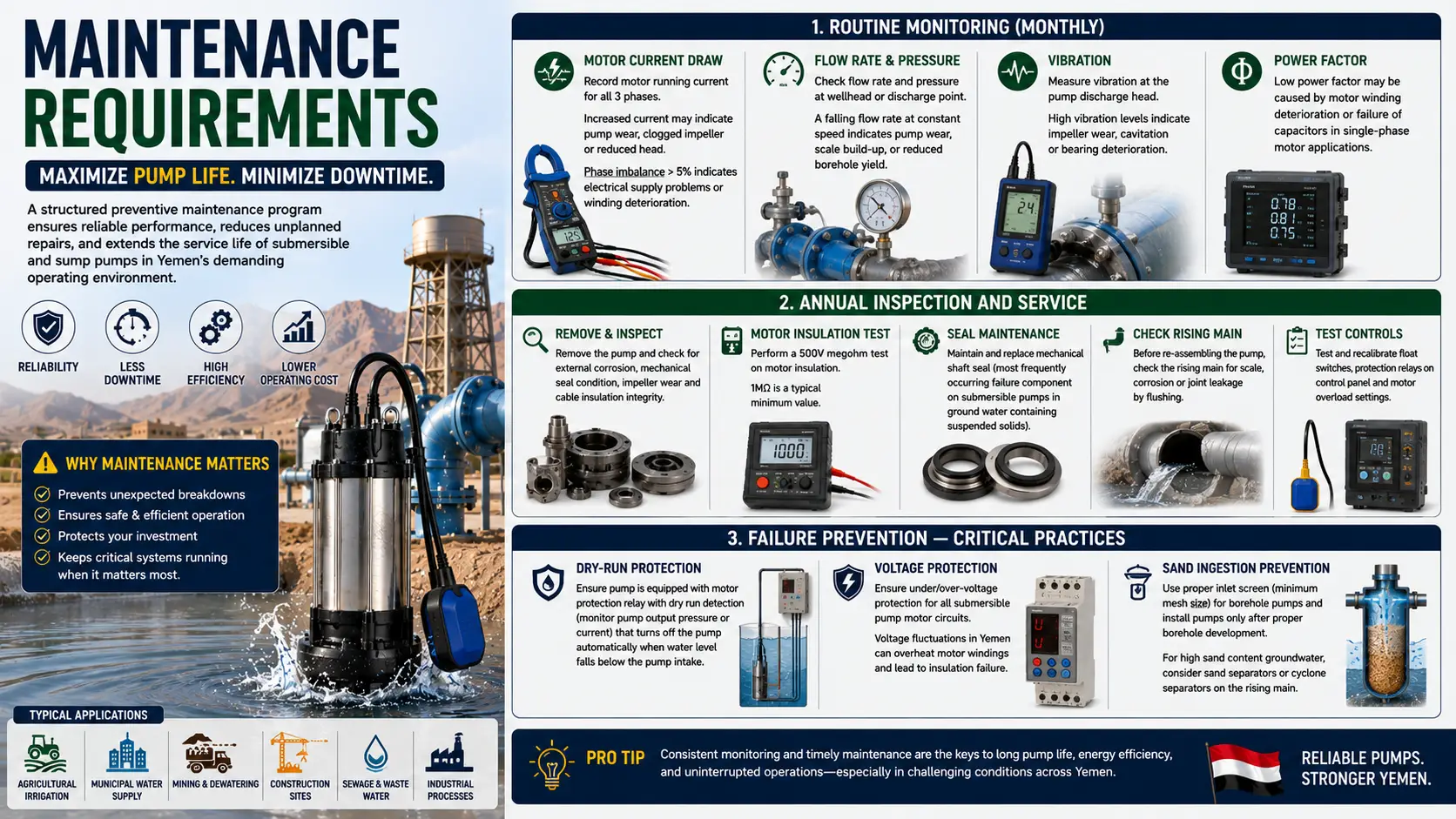
Maintenance Requirements
To ensure that the pump serves for the longest possible service life and that there is the least possible time on the bench for unplanned repairs, the industrial operator should have a structured program of preventive maintenance in place for his pumps. Sadly, one of the main reasons for premature pump failure in Yemen's operating environment is due to improper or neglected maintenance.
Routine Monitoring (Monthly)
Motor current draw: Record motor running current for all 3 phases. If the current is increased, the pump is worn, or the impeller is clogged, or the head decreases. A phase imbalance more than 5% is a symptom of electrical supply problems or winding deterioration.
Flow rate and pressure: Check flow rate from wellhead or discharge point and pressure. A falling flow rate at constant speed is a sign that the pump is becoming worn, or scale build-up on impellers or that the borehole is yielding less.
Vibration: Measure vibration at the pump discharge head. The higher the vibration level, the greater the wear on the impeller, cavitation or bearing deterioration.
Power factor: If power monitoring equipment is installed, a low power factor could be caused by motor winding deterioration or failure of the capacitors in single-phased motor applications.
Annual Inspection and Service
Remove the pump from the borehole or sump and check for external corrosion, mechanical seal condition, impeller wear and cable insulation integrity.
Perform a 500V megohm test on motor insulation (1MΩ is a typical minimum value). Reduced insulation resistance indicates that moisture is being allowed to get in or the windings are deteriorating.
Maintain and replace mechanical shaft seal (most frequently occurring failure component on submersible pumps in ground water containing suspended solids).
Before re-assembling the pump, check the rising main for scale, corrosion or joint leakage by flushing.
Test and recalibrate float switches, protection relays on control panel and motor overload settings.
Failure Prevention — Critical Practices
Dry-run protection: Ensure pump is equipped with motor protection relay with dry run detection (monitor pump output pressure or current) that turns off the pump automatically when water level falls below the pump intake, the most detrimental operating condition for submersible pumps.
Voltage protection: Ensure under/over-voltage protection for all submersible pump motor circuits. The voltage of the power grid in Yemen is often fluctuating and when it exceeds the motor's tolerance range of ±10% the voltage will overheat the motor windings and lead to insulation failure.
Sand ingestion prevention: To prevent sand ingestion, indicate the minimum mesh size of the inlet screen for borehole pumps, and only install pumps after the borehole has been well-developed. If the groundwater is a high sand type consider using sand separators or cyclone separators on top of the rising main above the pump.
Energy Efficiency Considerations
The majority of the energy cost is the single greatest expense for an industrial submersible pump installation during the pump's useful life. Optimizing pump efficiency is both a direct financial priority and a requirement for energy efficient submersible pumps in Yemen's projects where electricity is costly, provided by expensive generators or is intermittent.
Variable Frequency Drives (VFDs)
A Variable Frequency Drive (VFD) circuit can be installed on submersible pump motor circuits to provide speed proportional flow control without the requirement for throttle valves to be used to decrease the flow. Pump power consumption will be reduced by about 49% if the pump speed is reduced by 20%. Pump power consumption changes by a cube of the pump speed. VFDs can save 20-40% energy annually versus fixed-speed operation with throttle valves for municipal boreholes that are subjected to varying loads.
Motor Efficiency Class
When new pump installations are required, specifying IE3 or IE4 premium efficiency motors will result in a small upfront cost premium, but will provide energy savings of 3-6% over IE1 motors over the pump's lifetime. The total energy saved by a pump operating 16 hours/day for 20 years is significant – and the payback time for the efficiency premium is often 2-4 years.
Solar Pump Systems in Yemen
Solar-powered submersible pumping is particularly cost-effective for off-grid areas in Yemen because of its high solar resource, especially in terms of Global Horizontal Irradiance (GHI) of 5.5–7.0 kWh/m²/day for most areas. Agricultural borehole water pump projects in remote regions of Yemen, which are currently using diesel generators, can see their payback period shortened to 3-5 years with the introduction of a solar pump system with a near zero operating cost thereafter. The utilization of solar pumps in scale has been proven technically and economically successful, as it has been introduced in various agricultural areas in Yemen by various international organizations, such as UNDP and GIZ.
Factor | Solar Submersible Pump | Electric (Grid) Submersible Pump |
Power Source | Solar PV panels | Grid electricity or generator |
Operating Cost | Very low (after installation) | Ongoing electricity / fuel cost |
Initial Cost | Higher (panels + controller) | Lower |
Best For | Remote, off-grid locations | Grid-connected urban / industrial |
Flow Consistency | Varies with solar irradiation | Constant (grid-connected) |
Storage Option | Battery or water tank buffer | Not required |
Maintenance | Panel cleaning + pump service | Pump and motor service only |
Yemen Suitability | Excellent (high solar irradiation) | Good where grid is reliable |
Typical Application | Rural irrigation, village water | Urban supply, industrial facilities |
Lifecycle Cost Comparison
The cost of the groundwater pumping system project in Yemen must be calculated on the basis of the total life-cycle cost, and not the purchase price. In the majority of cases a higher quality, more efficient pump will have a lower life cycle cost than a lower cost pump of lower efficiency and higher maintenance requirements.
Cost Factor | Borewell Pump | Dewatering Pump | Sewage Pump |
Initial Capital Cost | Moderate–High | Moderate | Moderate |
Energy Consumption | Moderate (efficient multi-stage) | High (high flow demand) | Moderate |
Maintenance Interval | Annual or 2,000 hr service | 500–1,000 hr (heavy duty) | Annual |
Primary Wear Parts | Bearings, impellers, seal | Impellers, seal, wear plates | Impellers, seals |
Expected Service Life | 10–20 years | 5–10 years (abrasive duty) | 8–15 years |
Spare Parts Availability | Good (standard sizes) | Good | Good |
Downtime Risk | Low (correct installation) | Moderate (abrasive wear) | Low–Moderate |
The lesson to be learned from lifecycle analysis is that energy cost over the service life of the pump is generally 60–80% of the total pump ownership cost (excluding the initial capital cost). Each percentage point of efficiency gain equates to a cut in operating cost for the life of the asset. That's why it makes best economic sense to specify pumps at or near their Best Efficiency Point and invest in VFDs when there is variation in demand.
Future Trends in Industrial Pumping for Yemen
Smart Pump Monitoring and Remote Diagnostics
There are more and more submersible pump systems with built-in IoT sensors and GSM data loggers available for Yemen's infrastructure projects, and they are becoming more economical. These systems send real-time performance information — such as flow rate, motor current, vibration, temperature and operating hours — directly to cloud-based monitoring platforms, accessible via mobile. Distributed borehole infrastructure in Yemen provides access to maintenance on-site which is very difficult and expensive, therefore remote monitoring facilitates condition-based maintenance scheduling, as well as early detection of developing failures before catastrophic breakdown.
Solar-Diesel Hybrid Pump Systems
Where the grid or generator is available only during part of the day, solar-diesel hybrid pump controllers can be used to supply pump power from the solar PV system during the daylight hours, and automatically switch to supply from the grid or generator when solar generation is not adequate. Such hybrid systems achieve significant fuel savings and are suitable for continuous pumping operation without any interruptions — which is a limitation in pure solar systems used for municipal or industrial continuous-duty pumping.
Energy Recovery and Water Reuse
With increasing water shortages in Yemen, efforts are placed on extracting water at its highest possible utility. Trends are: Agriculture and processed water for irrigation with properly designed submersible pumps for treated wastewater; and energy recovery in the high-pressure distribution systems by inline micro-hydro turbines.
Common Pump Selection and Installation Mistakes to Avoid
Oversizing the Pump
Ineffective pump selection is employing a pump with much greater flow than is needed. The oversized pump will be operating at the low end of the pump curve where vibration, bearing load, recirculation in the impeller, and cavitation are all high. Appropriate sized pumps, run near the BEP at normal operating conditions will provide longer service life, lower energy consumption, and lower maintenance costs.
Ignoring Water Quality Data
It is a mis-judgment to choose pump materials without water quality analysis. A cast iron pump installed in brackish or mildly saline groundwater can deteriorate in months, and be forced to be replaced – a cost far more than the premium that would have been charged for a stainless steel, submersible pump that Yemen would have specified initially. Always get water quality information before making final material selection – pH, EC, chloride, sulphate and iron/manganese.
Incorrect Rising Main Sizing
If the rising main pipe is too small, too much friction loss will occur which will result in lower head and flow than the design. This is characterized by a pump that appears to have poor performance while it actually performs well. The pipe friction calculation depending on the pipe material and diameter should be used to ensure flow velocity of pipe is maintained between 1.0 and 2.0 m/s during design flow rate.
Neglecting Voltage Protection
The electrical supply system in Yemen has severe voltage fluctuation. When the submersible pump motor operates at continuous under voltage (-10% or less), the motor begins to overheat the winding, which will reduce the life of the motor by damaging the insulation. In areas where the electric power supply is not reliable, voltage protection relays represent an inexpensive insurance policy to avoid the replacement of motors over and over.
Installing Without a Qualified Borehole Survey
Installing a pump into an unsurveiled borehole (casing conditions, depth, static water level, borehole yield and water quality) presents a high risk. Folded or corroded casing can cause entrapment of a pump in the borehole and the pump can be retrieved only with great difficulty. It is important to have a borehole survey conducted prior to specifications and ordering of a pump by a qualified hydrogeologist or borehole contractor.
Frequently Asked Questions
What are industrial submersible pumps used for?
Yemen industrial submersible pumps applications include: dewatering from boreholes, transfer of irrigation water for agriculture, municipal drinking water supply, dewatering for mines and constructions, transfer of sewage and wastewater, and transfer of process water for industry. Submersible pumps are essential water infrastructure in all of these sectors in Yemen, where water is scarce.
How does a submersible pump work?
A submersible pump has its full body immersed in the liquid that it pumps. The whole pump is encased in an electric motor which rotates an impeller that throws fluid outward through centrifugal motion. This creates a pressure that forces the fluid back up the discharge pipe. The surrounding fluid cools the motor and it is hermetically sealed to ensure that water does not enter the motor.
What is the most suitable deep well submersible pump?
Multistage bore well submersible pumps are the right technology for deep borehole applications in Yemen. Pumping can be carried out at depths of over 300 meters, using multiple impeller stages that are stacked in series. Usually, 4-inch or 6-inch configuration submersible pumps are employed in the stainless steel construction for use in agriculture and municipal pumps in Yemen.
What is the difference between borewell and sewage pump?
Borewell pumps are designed to extract clean water from boreholes and groundwater sources. They do not work with solids and employ enclosed multistage impellers. Sewage pumps must be designed to handle solids, fibrous material and sludge, and should have either large-passage vortex impellers or single-channel impellers that will not be affected by solids passing through it. A borewell pump will rapidly get clogged and fail if sewage or dirty water is used.
What is the lifespan of a submersible pump for an industry?
The service life of a pump depends on the type of pump, operating conditions, water quality and maintenance quality, and, when properly selected, installed and maintained, an industrial submersible pump has a service life of 8–20 years. Maintained borewells with clean groundwater are commonly able to run for over 15 years. For abrasive service, it is only 5-10 years for the life of the dewatering pumps in general, depending on the degree of solids content.
Why do you think a submersible pump fails?
Dry running — overheating of the motor due to a low water level below the water inlet of the water pump
Power surges — spike in voltage that causes motor windings to become damaged by the high voltage.
Abrasion of impellers and wear rings caused by ingestion of sand and solids.
Pump sizing — vibration and bearing damage due to operation outside of BEP
Failure of mechanical seal – water entering motor due to failure of seal.
The problems listed above can be prevented by avoiding corrosion, which occurs when the wrong materials are used for the water chemistry.
In what ways are stainless steel pumps superior to cast iron pumps?
In applications where the groundwater contains brackish water, saline or mineralized groundwater, which are typical in coastal areas and deeper aquifers then there is no doubt about the superiority of stainless steel 316L and it is always necessary to specify. If the application is for fresh water and the pH is controlled and chloride levels are low, cast iron pumps will serve as well and cost less. If water quality data is not available, stainless steel is a conservative and recommended material.
Will submersible pumps work in dirty water?
Dirty water will cause impeller wear and possible blockage in the standard borewell pumps. The water containing sand and silt particles, suspended solids have been designed for use of dewatering pumps where wear resistant impeller materials are used. Sewage pumps are used to pump wastewater that contains solid matter, rags and sludge, and they use a large-passage impeller design.
What is the maximum depth at which a submersible pump can work?
Industrial multistage submersible borewell pumps can be used to a depth of over 300 meters and some specialist deep well pumps are rated for depths of 500 meters or more. In water scarce areas, for industrial groundwater pumping applications, the selection of the pump needs to be verified for the terrain's maximum pumping depth, ensuring that the pump head rating matches the total dynamic head of the pumping application.
Is there any pump that is solar-powered and submersible?
Yes. Solar submersible pump systems are readily available, and are increasingly being called for for rural and agricultural use in Yemen, where there is no electricity grid. Solar pumping is economically viable in Yemen owing to the high solar irradiance in the region and many solar pumping deployments have been implemented through UNDP and international NGO program in the farming regions. Solar pump systems include the appropriate sized PV array for the submersible pump motor, and MPPT controllers.
When do you need to service submersible pumps?
For most industrial submersible pump applications, annual inspection and service is recommended and monthly monitoring of the motor current, flow and vibration is recommended. In high duty or abrasive service applications, inspection intervals that are greater than 6 months may be needed. The best approach to maximizing pump life and minimizing unplanned downtime is to have a structured preventive maintenance program in place.
What points should be taken into account before buying submersible pump?
The factors taken into consideration are: required flow rate, T.D.H. required, fluid characteristics (water quality, temperature, solids contents), installation constraint (borehole diameter, sump size), power supply characteristics (Voltage, frequency and availability), applicable material standards, motor efficiency class, protection rating, spare parts availability in Yemen, and total lifecycle cost (energy, maintenance, and expected service life).
What is meant by pump head?
Total Dynamic Head (TDH) = Static Head + Friction Head Losses. The sum of the vertical distance from the water level at the pumping point to the point at which the water is discharged from the pump is referred to as Static Head. Friction Head Losses are determined by the Hazen-Williams or Darcy-Weisbach equation, which takes into account pipe internal diameter, pipe material roughness, pipe length, and design flow rate. For standard pipe size and types, this can be done easily using online calculators for pump heads and/or engineering reference tables.
In which part of Yemen is Industrial Submersible Pump used?
Industrial applications of submersible pumps in Yemen include agricultural borehole water for highland and Tihama agricultural areas, municipal water supply boreholes in Sanaa, Aden, Taiz, and secondary cities, industrial water supply for free zone of Aden and mineral-producing areas, industrial water supply for industrial areas of Mukalla, construction dewatering at project sites, and wastewater lift stations operated by municipal authorities in the city of Aden and Al Hudaydah.
How We Support Pump Procurement for Yemen Projects
As an independent industrial source and procurement company, we support procurement engineers, project managers, NGO's infrastructure teams and municipal teams in Yemen and the MENA region in identifying and sourcing quality industrial submersible pumps Yemen projects need. Technically speaking, we have no allegiance to any particular brand, and we do not endorse any product in particular, but we can assist our clients in selecting products from the worldwide market by helping them find options that fit their specifications, certifications and delivery schedules.
Our procurement support includes borewell pumps, dewatering pumps, sewage pumps, solar submersible pump systems, and components for the water, agriculture, mining, municipal and industrial sectors of Yemen.
Related guides: Centrifugal Pumps in Kuwait | Cement Plant MRO Supplies in Pakistan | More Industry Insights
DISCLAIMER: Z&F Corporation is not affiliated with, authorized by, endorsed by, or acting as an official representative of any manufacturer, brand, or trademark owner referenced on this website. All product names, trademarks, brand names, logos, and manufacturer references are the property of their respective owners and are used solely for identification, reference, and compatibility purposes.